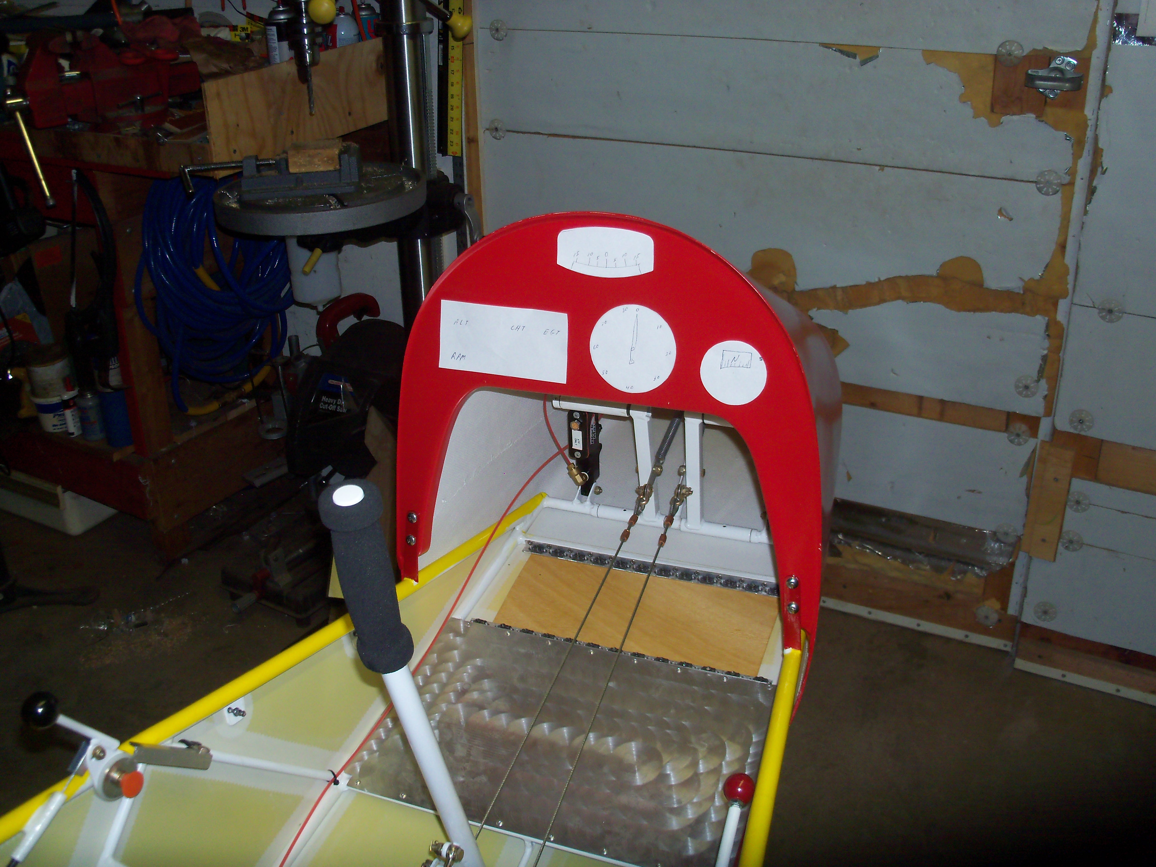
Click on any of the photos below to see the full size image.

Warning, they are fairly large to download. Use your browser's back button to return here.


 image


Layout

The ASI, Compass and Bank Indicator were purchased at Oshkosh, but the EIS had to be ordered. At this point all I had to go by were the dimensions provided by GRT.

Paper cutouts were used to try different configurations. This is the one I settled on.

 image

The First Cut

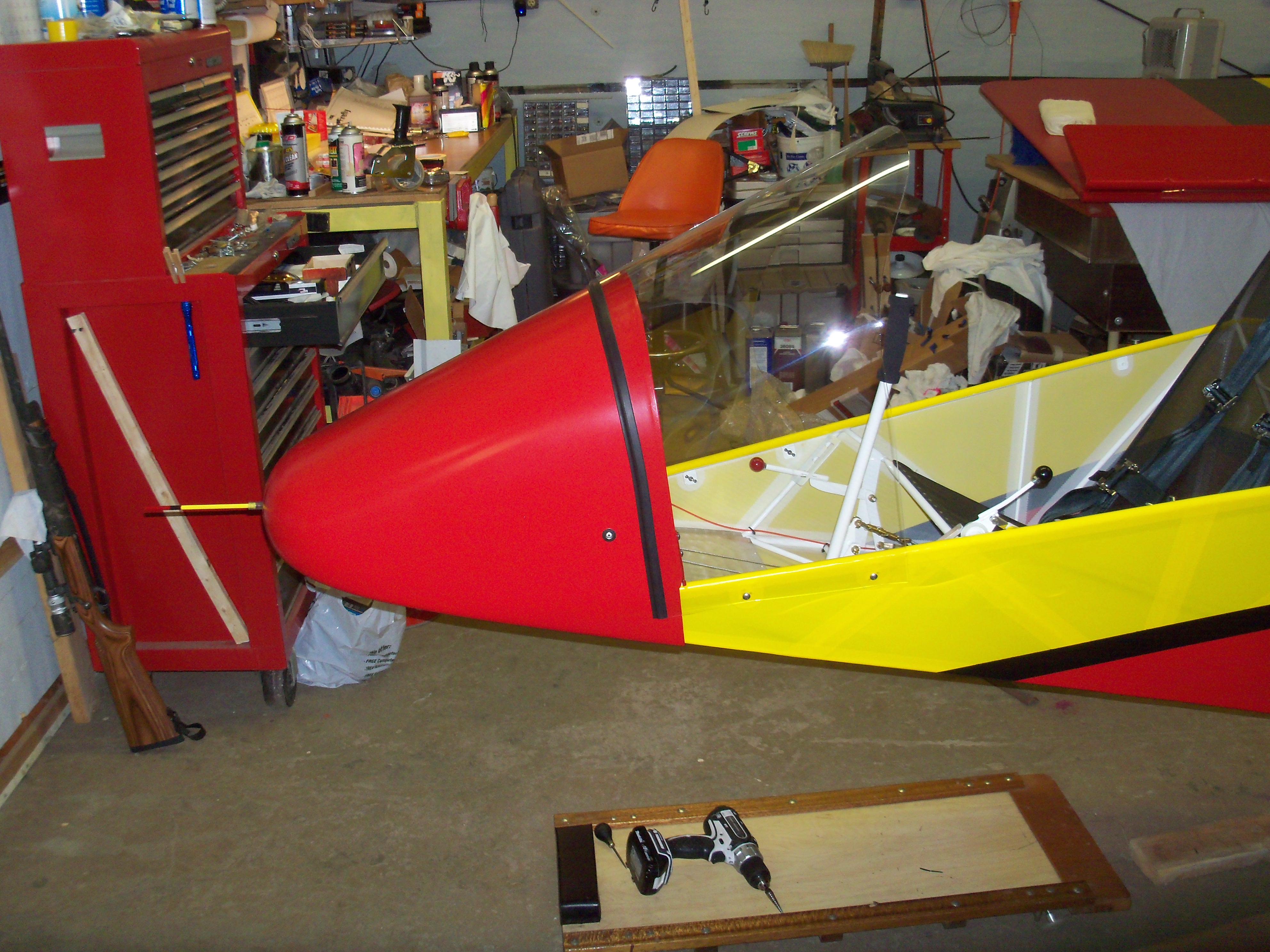
After all the work it took to get the nose cone to this point, making the first cut was quite nerve racking. Much research was done to try and figure out the best way to make these cuts. Almost everyone has a different idea.

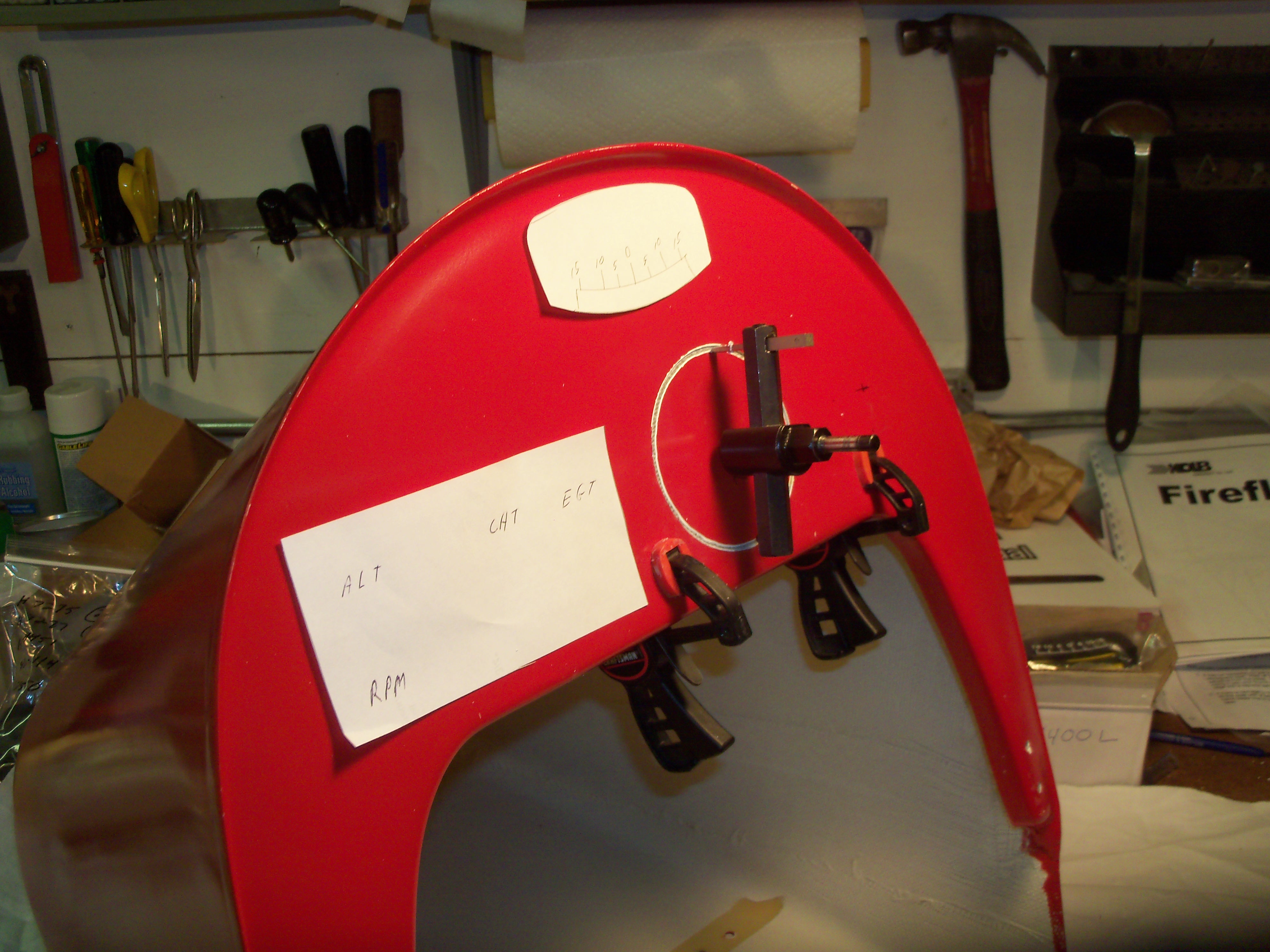
The drill press and hand drill were both too unstable with the fly-cutter, so I just turned it by hand. I had to sharpen the cutter several times as the fiberglass dulled it quickly. Eventually it left a clean hole.

For the compass, I used a carbide cutter in my Dremel Tool and just went very slowly.

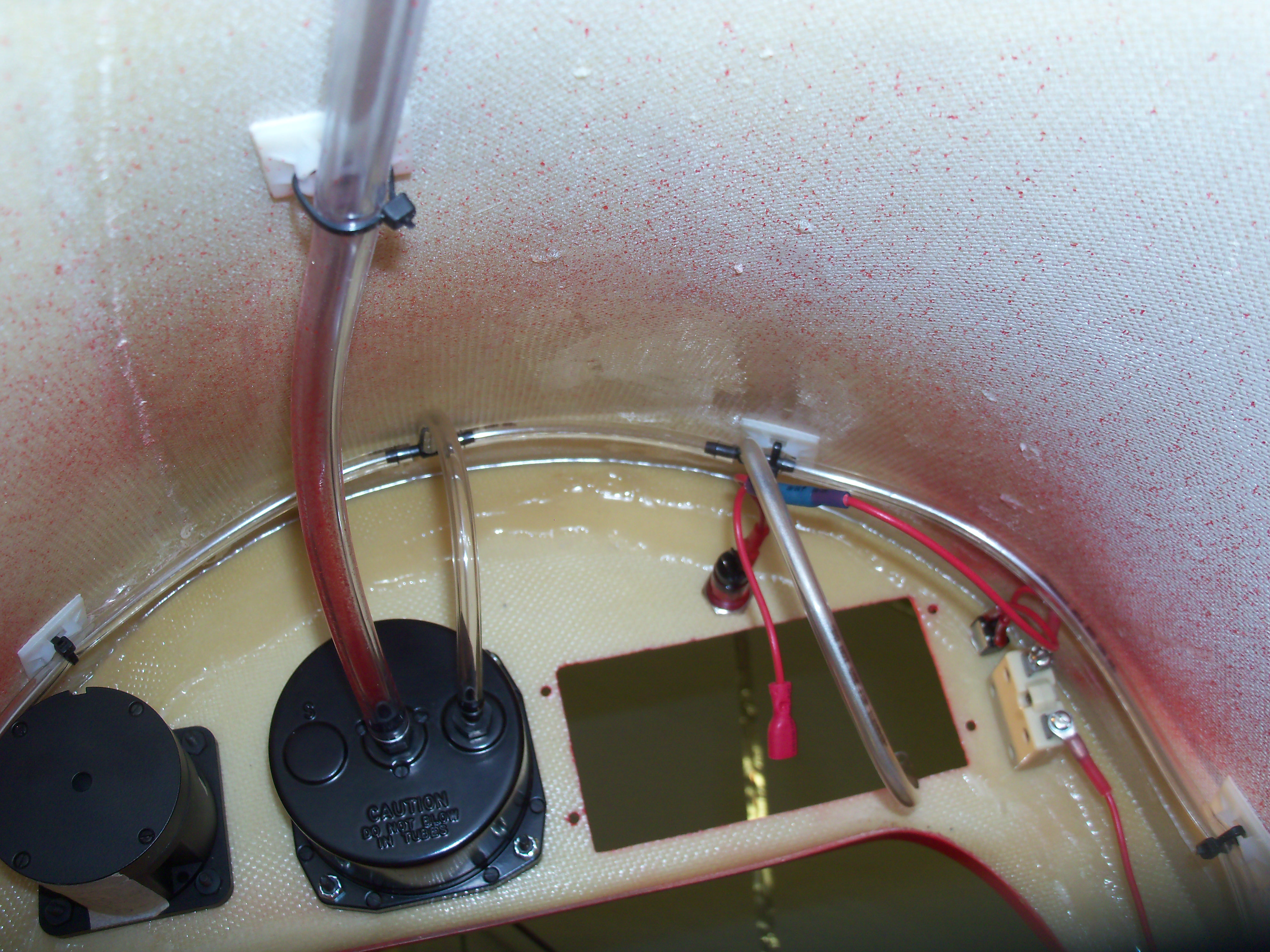
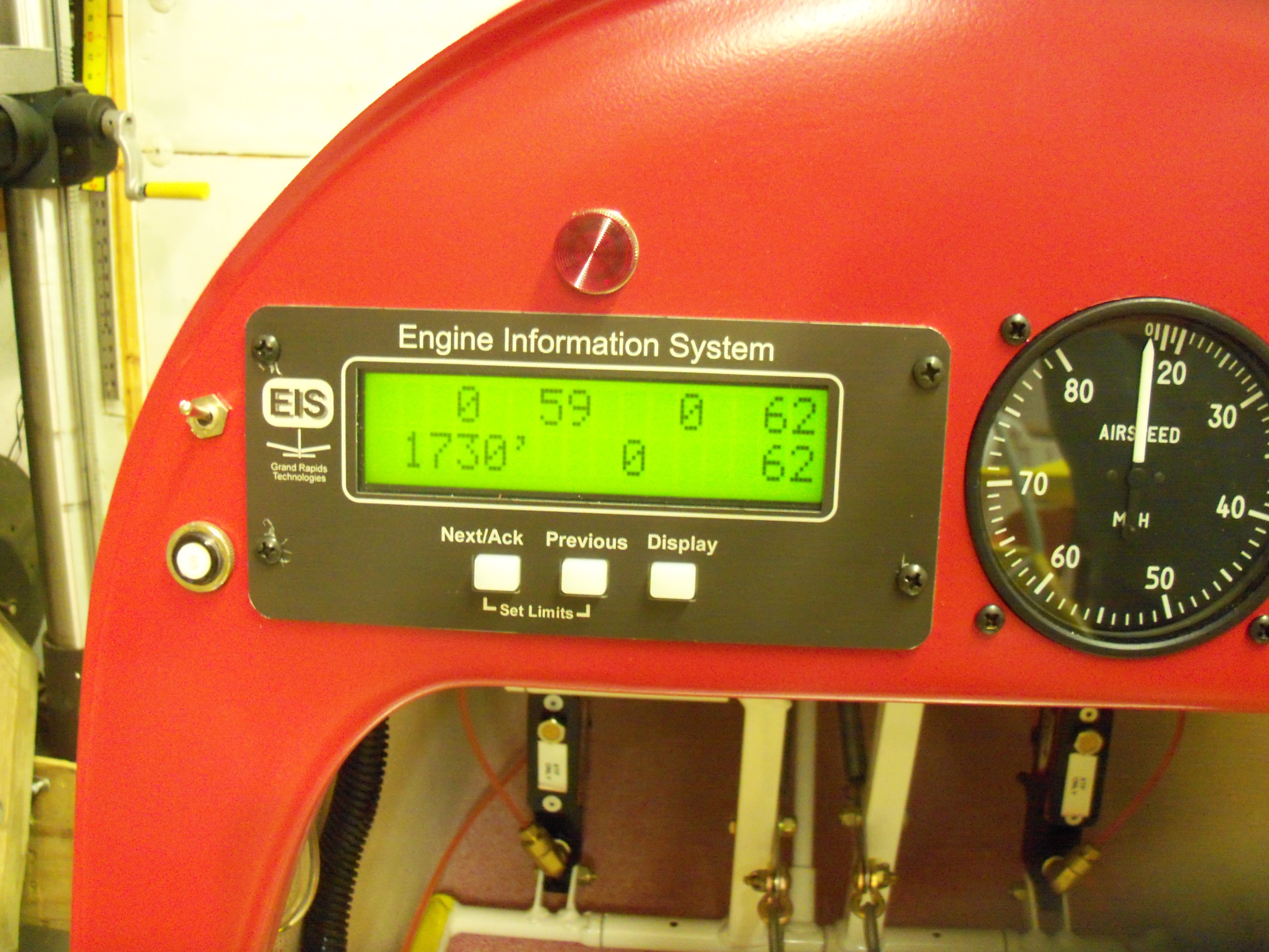
Once the EIS unit arrived, I used a combination of cutoff wheel and carbide cutter for that hole.

 image


Back View

Here you can see the pitot and static lines for the ASI and the wires for the EIS.

The EIS would have worked with only an inline fuse, but I opted to mount a circuit breaker and power switch on the panel. I had both of them on hand anyway.

 image


Pitot

This is pretty much exactly as per the Firefly instructions.

It actually makes a neat, out-of-the-way installation.

Simple too!

 image

Pitot and Static

There are lots of opinions/options for a static source in a Kolb. I found this idea on a web site (credit would be given if I could remember where). It uses a rivet of a size that will fit the ID of the tubing you use after the rivet has been expanded. I also used a stainless steel countersunk washer under the rivet. Drill a hole large enough that the washer will lay flat on the outside. In this case the tapered portion of the washer was just as thick as the fiberglass so a second washer on the inside allowed it to tighten up without breaking. Then you just use a small punch and punch the anvil out of the rivet. Viola! An instant static port for pennies.

 image

Wires and Static Fitting

The EIS uses a 25-pin connector that is held on with screws for all the wires. I had to jump out of the harness to run power through the circuit breaker and switch. A single spade connector allows easy removal of the nose cone. Just loosen the two screws on the large connector and pull the spade connector apart to leave all the wires on the plane. The nose cone is easily removed by taking out all the screws.

This makes for much easier access to the instruments. I would rather work upright at the bench than upside down, standing on my head, wiggled in around the stick.

 image


Switch

This is a standard kill switch for the engine. I had to change the labels because making contact (normal on) is what kills the engine by grounding the ignition module.

 image

EIS 2000 Module

This is a pretty cool instrument and gives you lots of information. The red light above it is a warning light that comes on when a reading goes beyond the programmed setting. It DOES get your attention!

Here it is powered up using a battery jumpered into the voltage regulator.

All the connections were confirmed by blowing a heat gun on the sensor and watching the displays to make sure the sensors were wired to the correct inputs. Also all the limits were programmed in before the engine was ever started.

 image

Cockpit View

Here is what the pilot sees.

My only complaint is the panel is so far away that I can not reach it when the shoulder harness is snugged up. I guess I need longer arms!

The bank indicator was installed later during weight and balance when the wings were level.

There sure isn't much between the pilot and, well, EVERYTHING!


Serenity Home HarnerFarm.net